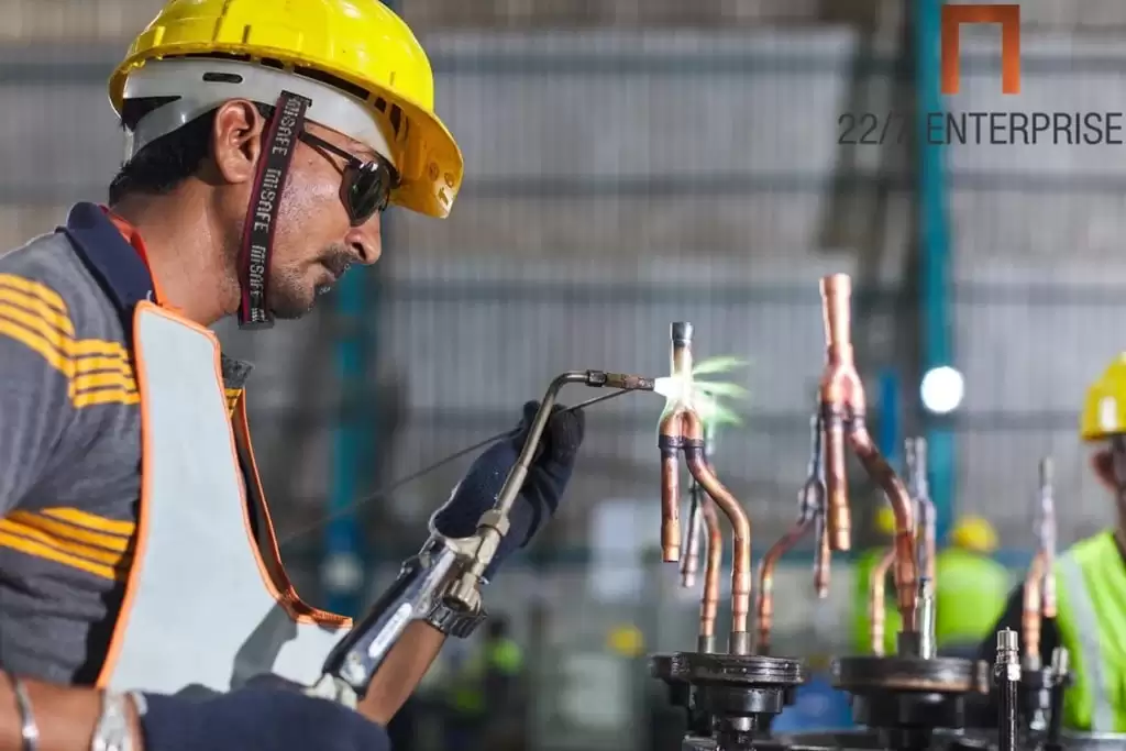
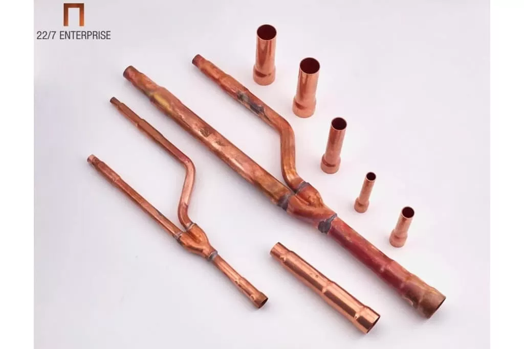
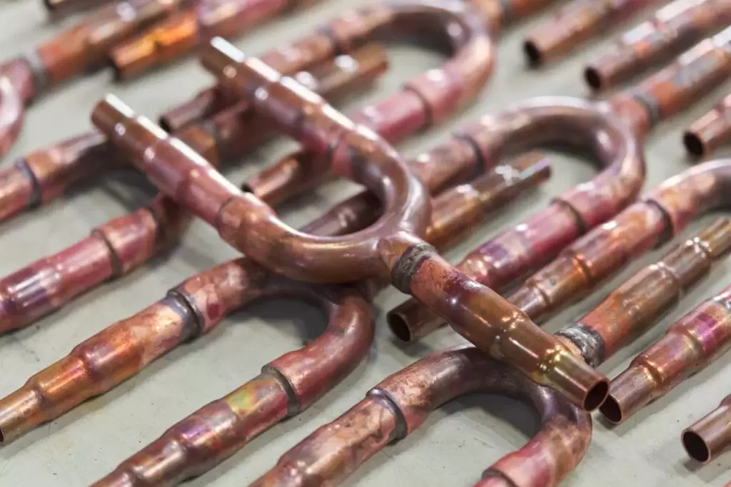
227 Enterprise – VRF Joints and Refrigerant Copper Fittings
Eng
Our Blogs
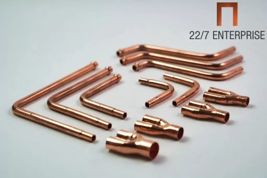
Universal Branch Pipe
DA Series
ME Series
MI Series
TA Series
GR Series
BSR Series
LG Series
HIT Series
HAE Series
CL Series
LNX Series
MHI Series
SAM Series
PNS Series
TRN Series
AX Series
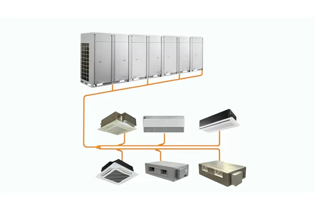
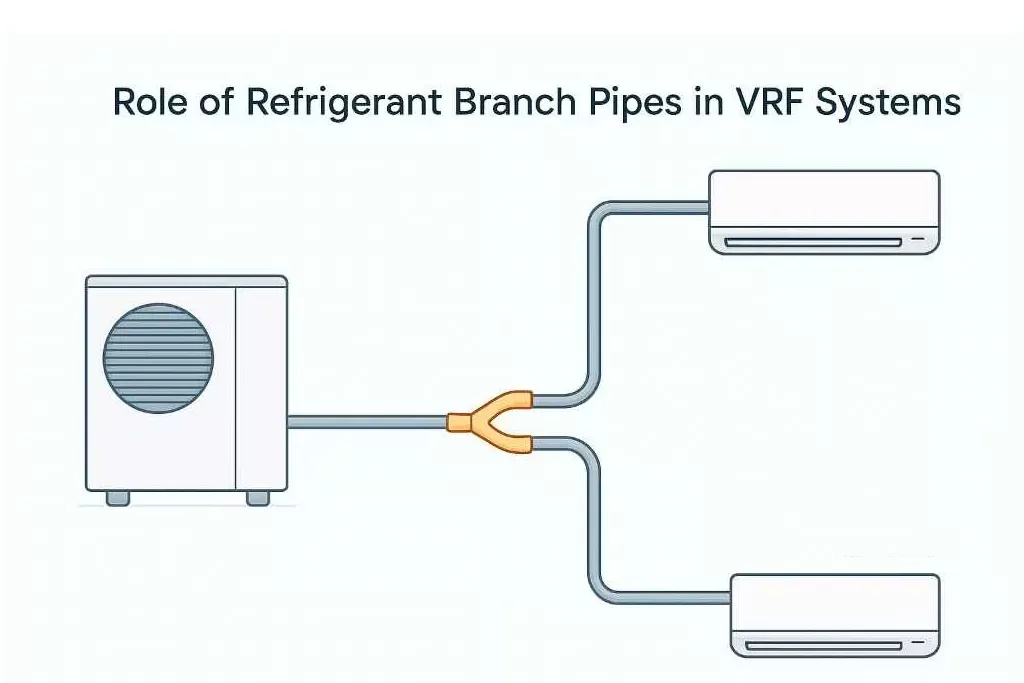
VRF Y Joint
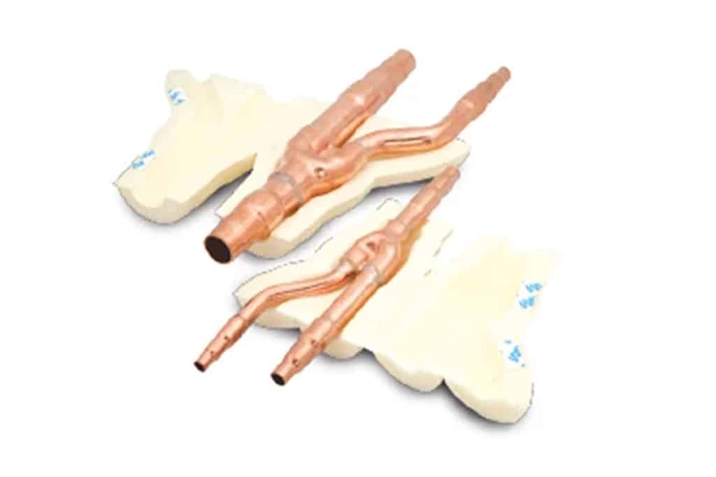
VRF Branch Piping
VRF Refrigerant Branch Piping
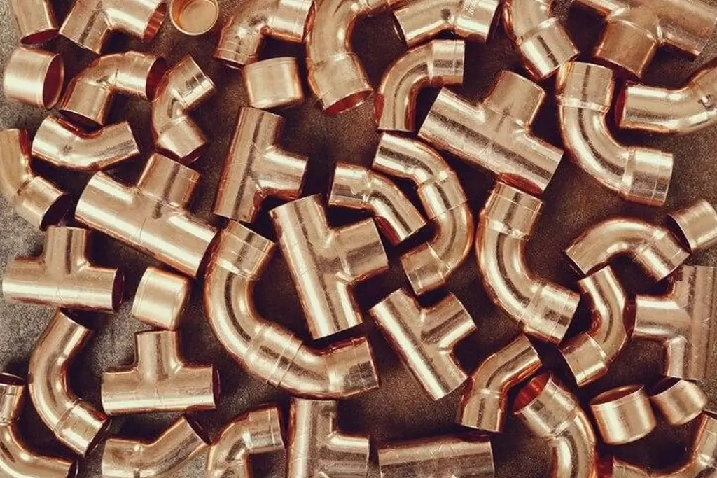
Copper Compression T Fitting
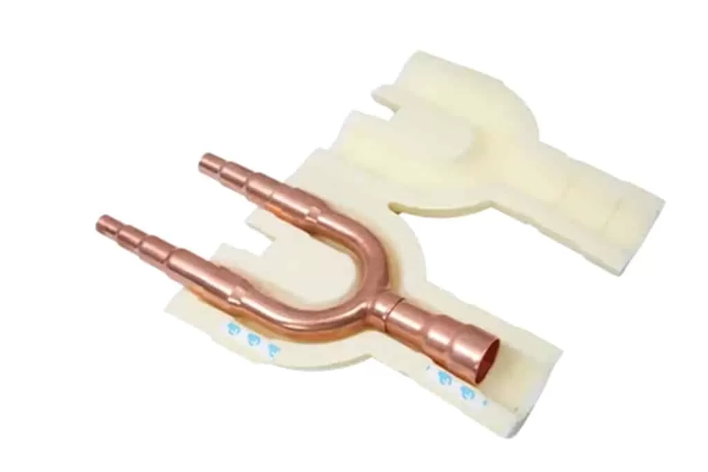
Copper Y Fitting
Strainers
Mufflers
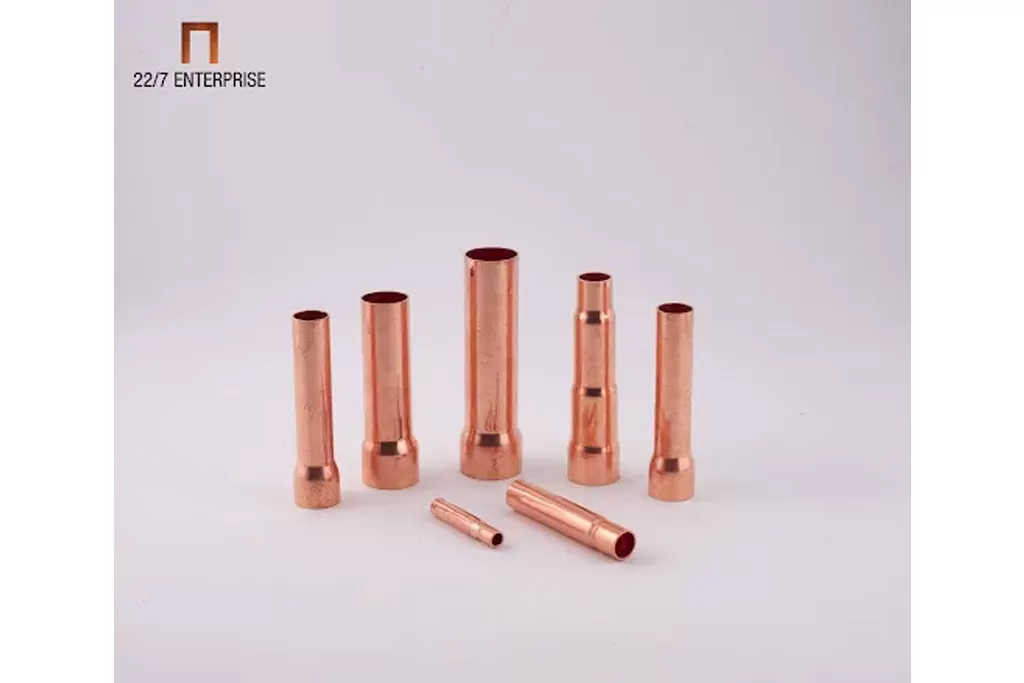
Stubs
Commercial Tee's
Copper Tee Joint
Y-Type Distributors
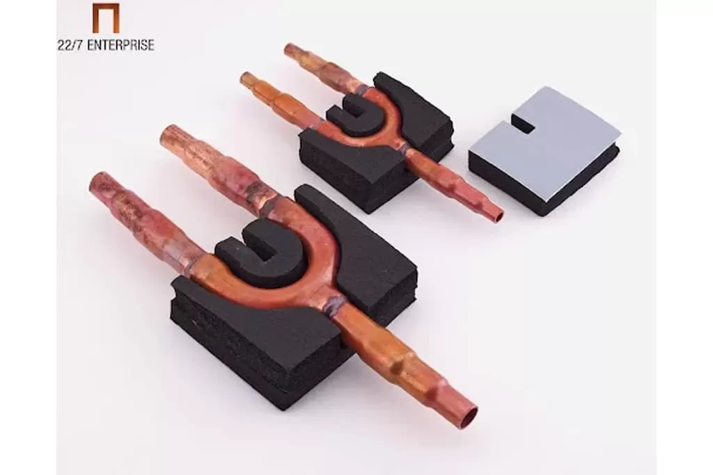
Unbrazed U & Y Fittings
Copper Y-Joint
Tubular Assemblies
SAM Headers
TA Headers
Customized Headers
EPS Insulation
NBR Insulation
XLPE Insulation
Customized Insulation